All used meshes were either produced by ourselves, or downloaded from the following internet adresses:
| Scene | Dragon |
|---|---|
| Number of Triangles | 902000 |
| Computer | Athlon XP X2 3200 |
| Strategy | Mean |
SAH |
||||||
|---|---|---|---|---|---|---|---|---|
| Tree Depth | 10 | 14 | 18 | 10 | 14 | 15 | 16 | 17 |
| Number of leaves | 1020836 | 1428114 | 3649625 | 953349 | 1042404 | 1082853 | 1133336 | 1197212 |
| Max leaf count | 2092 | 272 | 60 | 10982 | 1869 | 1523 | 972 | 662 |
| Number of empty leafs | 0 | 0 | 0 | 136 | 995 | 1688 | 2886 | 5043 |
| Tree Construction Time | 7s | 21s | 78s | 69 | 114 | 126 | 133 | 144 |
| Rendering Time | 215 | 50 | 24 | 120 | 17 | 14 | 16 | 15 |
Further, since the tree building time grew up with growing tree depth (even if runtime still in O(N log N)), we decided to implement a sampling algorithm, that saves the time for the N log N sorting of the list with all split positions. With a sampling count of 16 samples along the split direction the following results were obtained using different thresholds hwen to switch to normal complete scanning:
| Threshold | 800000 | 100000 | 30000 | 5000 |
|---|---|---|---|---|
Tree Depth |
15 | |||
| Number of Leafs | 1079532 | 1082433 | 1107008 | 1130325 |
| Max Leaf Count | 1414 | 1165 | 1073 | 873 |
| Empty Leaf Count | 1651 | 1757 | 2350 | 2948 |
| Tree Construction Time | 118 | 103 | 90 | 58 |
| Rendering Time | 139 | 124 | 102 | 70 |
50 p - by Oliver Source code 1 2
The idea in reflective refractive transparency is to simulate the bahviour of light rays incident to transparent materials. If a material is (semi-)transparent, a fraction of the light hitting this surface is refracted into the material. There two things are of most interest: First the direction of the refracted light and secondly the intensity of the refracted light. Depending on the optical density of the two involved materials, the propagation speed of light changes. By this difference (see Snell's law), the refracted ray is directed in a slightly different direction. For the second detail, the Fresnel equations give methematical answers to the fractions of reflected and refracted light intensities. See this webpage for detailed information.
30 p - by Nico Sourcecode Demo
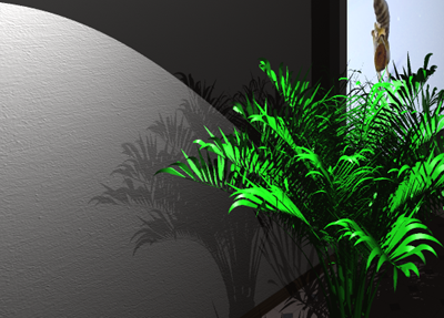
For simulating the surface structure of an object, Bump Mapping brings out very nice results without explicitly changing the real image surface. The surface of an object is discribed by their normals. So instead of changing the surface, Bump mapping changes the normales, disribing the surface. For that, the new surface structur is discribe by an additional Bump Texture. The spatial derivatives of the Bump Textures delivers the information for changing the normals of the surface.
30 p - by Nico Sourcecode
In order to use eventually present multiple CPU cores, the MicroTrace project needed some additions how to distribute the workload to different cores. Therefore, we first added all rays that have to be traced from the camera into the scene (i.e. Number of super sampled times number of pixels) to a list, which was then afterwards given to all threads. Each thread pops a job from the list and traces the ray. After that the result is written into the image. Impotant to notice is that the access to the list, as well as the access to the image has to be thread-save, i.e. one has to make sure that neither a job is done twice, nor a job is omitted. Moreover, the single static recusion depth variable "maxBounce" is not sufficient anymore.
30 p - by Oliver source code 1 2
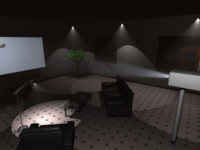
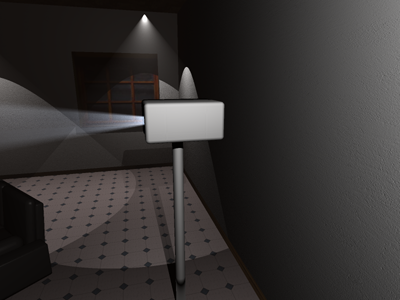
In the context of volume rendering, one has to understand: The way of a ray through the scene may intersect with an (or multiple) volumes. If this happens before the actual intersection with an solid object, then certain physical phenomena take place: First phenomenon is absorption. The color that has been shaded from the object (or if there was no intersection with an object, then the background color) is dampend. Secondly, what also occurs is out-scattering, i.e. light rays travelling from the hitpoint in ray direction hit small particles in the volume. By that they change their direction and will not arrive at the former destination. Also this phenomenon dampens the arriving radiance. The next physical phenomenon is emission, which reflects the volomes property to send out photons by itself. This enlargens the arriving radiance. The last (and very important) phenomenon is inscattering: As the ray travels its way, the light sources of the scene send out photons (that do initially not travel into the rays direction. But if such photons hit particles in the voulume they may be scattered into the ray direction and by that add a contribution to its radiance. Besides, to get acceptable runtimes, we had to introduce optimised sampling, ie. Ray-Spotlight-Cone intersections as done here
40 p - by Oliver source code 1 2 3 4 5
In order to simulate glossy reflections, or partial reflections, it is not sufficient anymore (in contrast to the Phong shader) to simulate this via some material properties. What has to be done is to shoot additional rays. Since glossy reflections look blurry in general, which originates in reality from material roughness, it is necessary to integrate over some solid angle. In order to do this, the direction vector of the perfect reflection ray is transferred into spherical coordinates (which results in two angles phi and theta). Afterwards, the two angles are deteriorated by some random component and transferred back into cartesian coordinates.
30 p - by Nico source code Demo
The Cook-Torrance shader is an addition extension to the phong shader. This shader allows a correct describition of physically rough surface like metal. In this model, the surface is treated as mircofacets which delivers more realistic reflection properities of metallic materials.
20 p - by Nico source code